Home |
IP Addressing |
Subnetting by the Numbers |
Paper Calculator
NAT |
CIDR |
IP Calculator |
VLSM Calculator
Variable-Length Subnet Masks (VLSM)
This page discusses VLSMs and how they can be used to further maximize IPv4 addressing efficiency.VLSM allows an organization to use more than one subnet mask within the same network address space. Implementing VLSM is often called subnetting a subnet. It can be used to maximize addressing efficiency.
Consider Table 1, in which the subnets are created by borrowing 3 bits from the host portion of the Class C address, 207.21.24.0.
Table 1- Subnetting with One Mask
| Subnet Number | Subnet Address |
| Subnet 0 | 207.21.24.0/27 |
| Subnet 1 | 207.21.24.32/27 |
| Subnet 2 | 207.21.24.64/27 |
| Subnet 3 | 207.21.24.96/27 |
| Subnet 4 | 207.21.24.128/27 |
| Subnet 5 | 207.21.24.160/27 |
| Subnet 6 | 207.21.24.192/27 |
| Subnet 7 | 207.21.24.224/27 |
If the ip subnet-zero command is used, this mask creates seven usable subnets of 30 hosts each. Four of these subnets can be used to address remote offices at say, Sites A, B, C, and D.
Unfortunately, only three subnets are left for future growth, and three point-to-point WAN links between the four sites remain to be addressed. If the three remaining subnets were assigned to the WAN links, the supply of IP addresses would be completely exhausted. This addressing scheme would also waste more than a third of the available address space.
There are ways to avoid this kind of waste. Over the past 20 years, network engineers have developed three critical strategies for efficiently addressing point-to-point WAN links:
• Use VLSMPrivate addresses and IP unnumbered are discussed in detail in these Study Guides. This section focuses on VLSM. When VLSM is applied to an addressing problem, it breaks the address into groups or subnets of various sizes. Large subnets are created for addressing LANs, and very small subnets are created for WAN links and other special cases.
• Use private addressing (RFC 1918)
• Use IP unnumbered
A 30-bit mask is used to create subnets with two valid host addresses. This is the exact number needed for a point-to-point connection. Figure 2-9 shows what happens if one of the three remaining subnets is subnetted again, using a 30-bit mask.
Classless and Classful Routing Protocols
For routers in a variably subnetted network to properly update each other, they must send masks in their routing updates. Without subnet information in the routing updates, routers would have nothing but the address class and their own subnet mask to go on. Only routing protocols that ignore the rules of address class and use classless prefixes work properly with VLSM. Table 2-6 lists common classful and classless routing protocols.
Classful and Classless Routing Protocols
| Classful Routing Protocols | Classless Routing Protocols |
| RIP Version 1 | RIP Version 2 |
| IGRP | EIGRP |
| EGP | OSPF |
| BGP3 | IS-IS |
| BGP4 |
Routing Information Protocol version 1 (RIPv1) and Interior Gateway Routing Protocol (IGRP), common interior gateway protocols, cannot support VLSM because they do not send subnet information in their updates. Upon receiving an update packet, these classful routing protocols use one of the following methods to determine an address's network prefix:
• If the router receives information about a network, and if the receiving interface belongs to that same network, but on a different subnet, the router applies the subnet mask that is configured on the receiving interface.Despite its limitations, RIP is a very popular routing protocol and is supported by virtually all IP routers. RIP's popularity stems from its simplicity and universal compatibility. However, the first version of RIP, RIPv1, suffers from several critical deficiencies:
• If the router receives information about a network address that is not the same as the one configured on the receiving interface, it applies the default, subnet mask (by class).
• RIPv1 does not send subnet mask information in its updates. Without subnet information, VLSM and CIDR cannot be supported.In 1988, RFC 1058 prescribed the new and improved Routing Information Protocol version 2 (RIPv2) to address these deficiencies. RIPv2 has the following features:
• RIPv1 broadcasts its updates, increasing network traffic.
• RIPv1 does not support authentication.
• RIPv2 sends subnet information and, therefore, supports VLSM and CIDR.Because of these key features, RIPv2 should always be preferred over RIPv1, unless some legacy device on the network does not support it.
• RIPv2 multicasts routing updates using the Class D address 224.0.0.9, providing better efficiency.
• RIPv2 provides for authentication in its updates.
When RIP is first enabled on a Cisco router, the router listens for version 1 and 2 updates but sends only version 1. To take advantage of the RIPv2 features, turn off version 1 support, and enable version 2 updates with the following commands:
Router(config)#router rip
Router(config-router)#version 2
Conventional Subnet masking replaces the two-level IP addressing scheme with a more flexible three-level method. Since it lets network administrators assign IP addresses to hosts based on how they are connected in physical networks, subnetting is a real breakthrough for those maintaining large IP networks. It has its own weaknesses though, and still has room for improvement. The main weakness of conventional subnetting is in fact that the subnet ID represents only one additional hierarchical level in how IP addresses are interpreted and used for routing.
The Problem With Single-Level Subnetting
It may seem "greedy" to look at subnetting and say "what, only one additional level"? However, in large networks, the need to divide our entire network into only one level of subnetworks doesn't represent the best use of our IP address block. Furthermore, we have already seen that since the subnet ID is the same length throughout the network, we can have problems if we have subnetworks with very different numbers of hosts on them - the subnet ID must be chosen based on whichever subnet has the greatest number of hosts, even if most of subnets have far fewer. This is inefficient even in small networks, and can result in the need to use extra addressing blocks while wasting many of the addresses in each block.
For example, consider a relatively small company with a Class C network, 201.45.222.0/24. They have six subnetworks in their network. The first four subnets (S1, S2, S3 and S4) are relatively small, containing only 10 hosts each. However, one of them (S5) is for their production floor and has 50 hosts, and the last (S6) is their development and engineering group, which has 100 hosts.
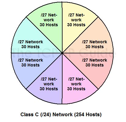
The total number of hosts needed is thus 196. Without subnetting, we have enough hosts in our Class C network to handle them all. However, when we try to subnet, we have a big problem. In order to have six subnets we need to use 3 bits for the subnet ID. This leaves only 5 bits for the host ID, which means every subnet has the identical capacity of 30 hosts, as shown in Figure 1 below. This is enough for the smaller subnets but not enough for the larger ones. The only solution with conventional subnetting, other than shuffling the physical subnets, is to get another Class C block for the two big subnets and use the original for the four small ones. But this is expensive, and means wasting hundreds of IP addresses!
Figure 1: Class C (/24) Network Split Into Eight Conventional Subnets

The Solution: Variable Length Subnet Masking
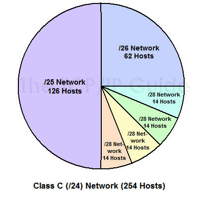
The solution to this situation is an enhancement to the basic subnet addressing scheme called Variable Length Subnet Masking (VLSM). VLSM seems complicated at first, but is easy to comprehend if you understand basic subnetting. The idea is that you subnet the network, and then subnet the subnets just the way you originally subnetted the network. In fact, you can do this multiple times, creating subnets of subnets of subnets, as many times as you need (subject to how many bits you have in the host ID of your address block). It is possible to choose to apply this multiple-level splitting to only some of the subnets, allowing you to selectively cut the "IP address pie" so that some of the slices are bigger than others. This means that our example company could create six subnets to match the needs of its networks, as shown in Figure 2 below.
Figure 2: Class C (/24) Network Split Using Variable Length Subnet Masking (VLSM)

An Example: Multiple-Level Subnetting Using VLSM
VLSM subnetting is done the same way as regular subnetting; it is just more complex because of the extra levels of subnetting hierarchy. You do an initial subnetting of the network into large subnets, and then further break down one or more of the subnets as required. You add bits to the subnet mask for each of the "sub-subnets" and "sub-sub-subnets" to reflect their smaller size. In VLSM, the slash notation of classless addressing is commonly used instead of binary subnet masks. VLSM is very much like CIDR in how it works so that's what I will use.
|
Key Concept: Variable Length Subnet Masking (VLSM) is a technique where subnetting is performed multiple times in iteration, to allow a network to be divided into a hierarchy of subnetworks that vary in size. This allows an organization to much better match the size of its subnets to the requirements of its networks. |
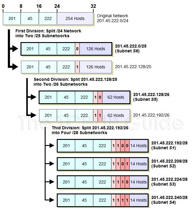
Let's take our example above again and see how we can make everything fit using VLSM. We start with our Class C network, 201.45.222.0/24. We then do three subnettings as follows (see Figure 3 below for an illustration of the process):
1. We first do an initial subnetting by using one bit for the subnet ID, leaving us 7 bits for the host ID. This gives us two subnets: 201.45.222.0/25 and 201.45.222.128/25. Each of these can have a maximum of 126 hosts. We set aside the first of these for subnet S6 and its 100 hosts.
2. We take the second subnet, 201.45.222.128/25, and subnet it further into two sub-subnets. We do this by taking one bit from the 7 bits left in the host ID. This gives us the sub-subnets 201.45.222.128/26 and 201.45.222.192/26, each of which can have 62 hosts. We set aside the first of these for subnet S5 and its 50 hosts.
3. We take the second sub-subnet, 201.45.222.192/26, and subnet it further into four sub-sub-subnets. We take 2 bits from the 6 that are left in the host ID. This gives us four sub-sub-subnets that each can have a maximum of 14 hosts. These are used for S1, S2, S3 and S4.
Figure 3: Variable Length Subnet Masking (VLSM) Example

Okay, I did get to pick the numbers in this example so that they work out just perfectly, but you get the picture. VLSM greatly improves both the flexibility and the efficiency of subnetting. In order to use it, routers that support VLSM-capable routing protocols must be employed. VLSM also requires more care in how routing tables are constructed to ensure that there is no ambiguity in how to interpret an address in the network.
As I said before, VLSM is similar in concept to the way classless addressing and routing (CIDR) is performed. The difference between VLSM and CIDR is primarily one of focus. VLSM deals with subnets of a single network in a private organization. CIDR takes the concept we just saw in VLSM to the Internet as a whole, by changing how organizational networks are allocated by replacing the single-level "classful" hierarchy with a multiple-layer hierarchy.
Here is another chart to help you see the VLSM IP ranges. Click HERE
